01
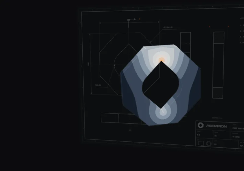
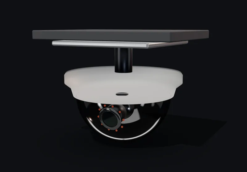
Resolved on paper first. Every concept is pinned down in orthographic views, sections and tolerances, so the intent is fixed before a single surface is modelled.
Inputs An idea, a sketch or a technical requirement Views Orthographic, section and detail views Tolerances Agreed per function and per process
02
Surfaces with continuity. High quality solid and parametric surface modelling to Class-A standards, checked with reflection lines so every highlight flows without a break.
Solid Parametric solid modelling Surface Class-A surface quality Check Zebra and reflection analysis
03
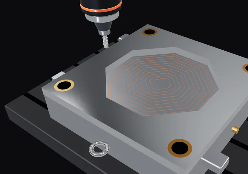
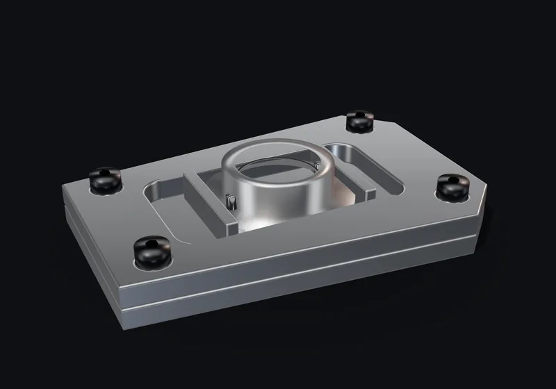
Designed for the process. Each part is modelled for how it will be made. Draft, wall thickness and undercuts are solved in CAD, not on the shop floor.
Moulding Draft angles, walls and undercuts Machining Tool access and setups Sheet metal Bend radii and flat patterns
04
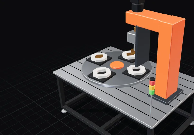
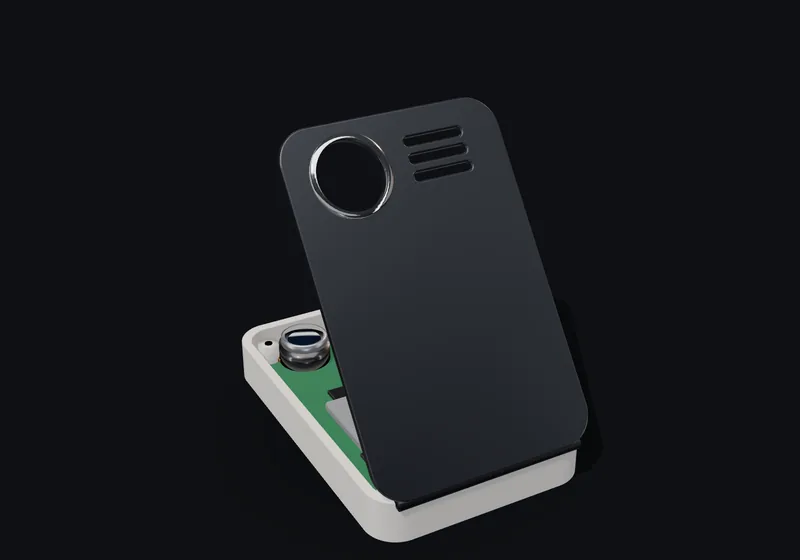
Proven before steel is cut. Moldflow predicts filling, warpage and cooling. FEA checks stress, deformation and load cases, so risks surface on screen instead of in the tool.
Moldflow Filling, warpage and cooling FEA Stress, deformation and load Output Report with design actions
05
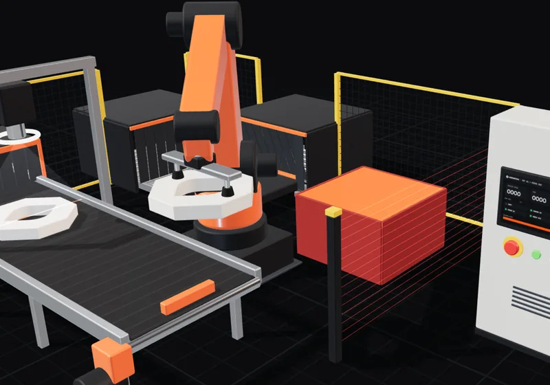
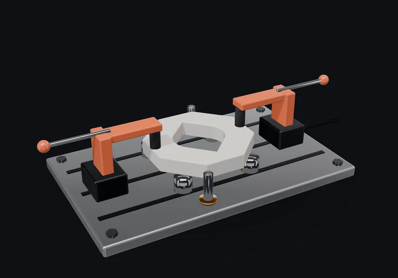
Held in hand, early. Rapid prototypes by SLA and SLS printing, or machined samples, used for fit, assembly and verification tests before tooling.
Additive SLA and SLS printing Machined Functional samples Tests Fit, assembly and validation
01 Drawing02 CAD03 DFM04 Simulation05 Prototype